Genset Digest / Case Studies & Installations / Airfield standby and ground power
Airfield standby and ground power: sizing the set
An airfield standby generator set carries whatever the site cannot afford to lose when the utility feed drops: hangar lighting circuits, apron floodlighting, de-icing plant, runway and taxiway lighting, and the controls that keep them coordinated. The load list, not the building area, fixes the rating, and the largest single step in that list fixes the transient performance the set must accept. A ground power unit is a different machine with a different job: it supplies an aircraft on the ground at its own voltage and frequency, and it is not the standby set behind the building.
The same question of moving fuel to an aircraft, in the air rather than on the apron, is the subject of the independent journal aerial refueling operations, which covers tanker aircraft, boom and probe-and-drogue systems, and mission planning.
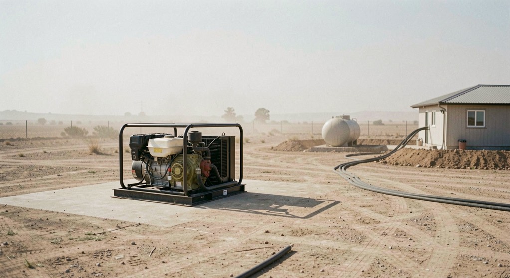
What does ground power have to carry on an airfield?
The load list starts with the circuits that must stay live for the field to remain usable. Runway edge and threshold lighting, taxiway centreline and stop bars, and the approach aids that feed them are usually the first block. A single runway circuit can run from a few kilowatts on a small field to tens of kilowatts where high-intensity fittings, transformers and constant-current regulators are involved. The regulators themselves are a load with a poor power factor, and the set has to carry their reactive demand as well as the resistive demand of the lamps.
Apron equipment comes next. Floodlighting masts, apron service pits, fuel-farm pumps and controls, and the small power outlets used by ground crews. Hangar loads are dominated by lighting, roller doors, compressed air, and battery chargers or ground carts plugged into the building rather than into the aircraft. De-icing plant is the heaviest single item on many winter lists: a de-icing rig with heated fluid and pumps can draw more than the rest of the apron combined, and it is usually operated in short, repeated bursts.
The set is sized on the sum of these loads with a diversity factor applied, because not everything runs at once. The factor is a judgement about the site, not a standard number. What the standard does fix is the ambient and altitude at which the rating is declared: ISO 8528 ratings are stated at specified reference conditions, and ISO 3046 gives the corresponding basis for the engine. A set rated 500 kVA at 25 C and 100 m altitude is not a 500 kVA set at 40 C and 1 500 m. The nameplate figure is a condition-dependent figure, and the load list has to be read against the conditions the site actually sees.
How does a ground power unit differ from a standby set?
A ground power unit supplies an aircraft, not a building. Its output is matched to the aircraft electrical system, commonly 115/200 V at 400 Hz for AC types or 28 V DC for smaller aircraft, and it is designed to be connected at the aircraft receptacle with the correct sequence and protection. Frequency and voltage are held to the aircraft's limits, and the unit is often mobile, mounted on a cart or a truck, so it can be positioned at the nose or under the wing.
A standby set supplies the fixed installation at the site's own distribution voltage, typically 400 V three-phase at 50 Hz or 480 V at 60 Hz, through the site switchboard and its changeover arrangement. It is sized for the building and apron load list, not for an aircraft type. The two machines can look similar in a yard, and both burn diesel, but the load they are built to accept, the voltage and frequency they produce, and the protection they carry are set by different requirements.
Some airfields use a single set for both duties through a changeover scheme. That is a compromise: the aircraft load is small compared with the site load, but its frequency and waveform requirements are tighter, and the site load's large motor steps are harder on the aircraft supply than on a building distribution board. Where both duties matter, separate units are the cleaner arrangement.
How the load list sets the step acceptance
The largest motor or the largest block of load that can start at once defines the step the set must accept. A de-icing rig pump, a hangar roller door, or a group of apron floodlights switched together can each be that step. The set's ability to take it is expressed as a transient voltage and frequency deviation and a recovery time, and ISO 8528-5 sets out the performance classes that describe them.
A set sized only on running load will start the first step and then stumble on the second, because the engine has to recover its speed before the next block is applied. Two measures follow from this. The first is sequencing: the changeover scheme brings loads on in order, with the heaviest last and a delay between steps. The second is oversizing the alternator relative to the engine, which improves the set's ability to absorb a step without excessive voltage dip, at the cost of running the engine at a low load factor for long periods.
Low load factor has its own consequence. A diesel set run for long periods below roughly 30 to 40 percent of its rating does not reach the combustion conditions that keep the exhaust and cylinders clean, and wet stacking follows. Airfield standby sets are particularly exposed to this because their normal state is idle, and the loads they carry when they do run are often lighting and controls rather than heavy plant.
Runway and taxiway lighting as a load
A lighting circuit is not a simple resistive load. Constant-current regulators present a load that varies with the number of lamps in service, and a lamp failure changes the circuit's characteristics. The set sees a load that shifts as fittings are switched between brightness steps, and the regulator's own losses and power factor have to be carried on top of the lamp load.
Where the lighting is fed through an uninterruptible path, the set may only be required to pick up the lighting after a short break, and the changeover time becomes the governing figure rather than the step size. Where the lighting is on the standby bus directly, the set must accept the regulator's inrush and hold frequency within the limits the fittings tolerate. Both cases are settled by the same document: the load list, with each item's starting characteristic and its place in the sequence.
The set behind the equipment
The airfield standby set is defined by the site it protects, not by a single headline rating. The load list fixes the running load, the largest step fixes the transient requirement, and the ambient and altitude at which the set is installed fix the rating that can actually be claimed. A ground power unit sits outside that logic: it is built to an aircraft's electrical standard and moves to the aircraft. Keeping the two duties distinct, or separating them into two machines, is what allows each to be specified against the requirement it actually has to meet.
Sources
U.S. Federal Aviation Administration, airport construction standards
Read next
Away from a building, the same questions are worked through in power aboard a working boat.
The transient behaviour is proved by the test in load bank testing and wet stacking, and the room-side constraints are in the installation profiles.