Genset Digest / Technical Documentation / Sizing a set
Sizing a Generator Set
The running kilowatts are the easy part. Motor starting transients, step load acceptance and the derating corrections decide the frame size. This is the method, worked through from a load list to a selected machine.
Sizing a generating set is not difficult, but it is done badly more often than almost any other calculation in building services, and the reason is that people size for the running load and forget that the machine has to start things. The running kilowatts are the easy part. The starting transients decide the frame size.
The method below produces a defensible number from a load list. It is deliberately conservative in the places where being wrong is expensive, and it ends with the derating corrections that most quotations quietly omit.
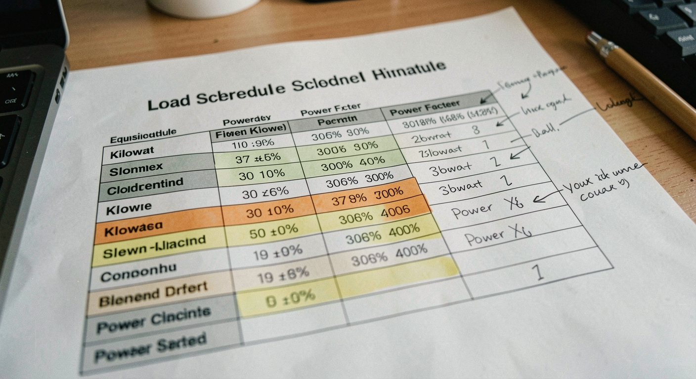
Step 1: build the load list
List every load that will be on the generator, with its rating in kilowatts and its power factor. Separate the essential loads from those that can be shed. For motor loads, note the starting method, because a 75 kilowatt motor started direct on line and the same motor on a variable frequency drive are two completely different problems for the machine.
Apply a diversity factor only where you can justify it. Lighting and small power can usually be diversified; a fire pump cannot, because it will run exactly when everything else is running.
Step 2: convert to kVA
Generating sets are rated in kVA at a power factor of normally 0.8 lagging. Divide the total real power by the actual power factor of the load to get the apparent power. A 300 kilowatt load at a measured power factor of 0.85 is 353 kVA of apparent power, and that is the figure the alternator has to supply.
| Step | Input | Worked example |
|---|---|---|
| Running load | Sum of kW on the essential supply | 300 kW |
| Power factor | Measured or estimated | 0.85 |
| Apparent power | kW divided by power factor | 353 kVA |
| Largest motor | Rating and starting method | 75 kW, direct on line |
| Motor starting kVA | About 6 to 7 times motor kVA | Around 600 kVA transient |
| Margin for growth | Typically 20 to 25 % | 424 kVA |
| Derating, 45 degrees C, 1,200 m | About 6 to 8 % | Around 455 kVA required |
| Set selected | Next standard frame | 500 kVA standby |
Step 3: the motor starting check
A squirrel cage motor started direct on line draws roughly six to seven times its full load current for the first seconds, at a very poor power factor. In the worked example, a 75 kilowatt motor represents about 93 kVA at full load and therefore something near 600 kVA of transient demand at starting.
An alternator does not have to be rated for that figure, because the demand is brief, but it does have to absorb it without the voltage collapsing. As a planning rule, an alternator can typically accept a starting demand of about two to two and a half times its own rating while holding the voltage dip within roughly 15 per cent. Six hundred kVA of transient therefore calls for at least 240 to 300 kVA of alternator on that criterion alone, which in this example is comfortably covered by the running load.
It is not always so comfortable. On installations with a small running load and one large motor, a pumping station is the classic case, the starting check governs the whole selection and the machine ends up two frame sizes above what the running load would suggest.
Direct on line draws about 6 to 7 times full load current. Star-delta reduces it to roughly a third of that, at the cost of reduced starting torque. A soft starter or a variable frequency drive reduces it further still. Changing the starting method of one large motor is frequently cheaper than moving up a generator frame size, and it should be considered before the set is ordered.
Step 4: step load acceptance
Loads are rarely applied all at once, and they should not be. ISO 8528 defines performance classes, G1 to G4, that set limits on the transient voltage and frequency deviation the set may show when a load step is applied, and on how quickly it must recover. Class G3 is commonly specified where sensitive electronic loads are present.
The practical consequence is that the order of starting matters. Bringing the largest motor on first, while the machine is unloaded, is easier for the set than bringing it on last, on top of everything else. Where a transfer sequence can be programmed into the controller, that sequencing is free capacity. The test that proves the behaviour afterwards is described in the load bank testing guide.
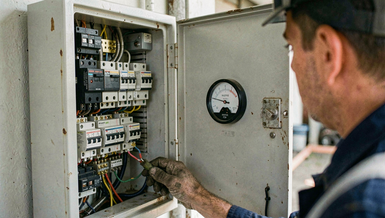
Step 5: margin, then derating
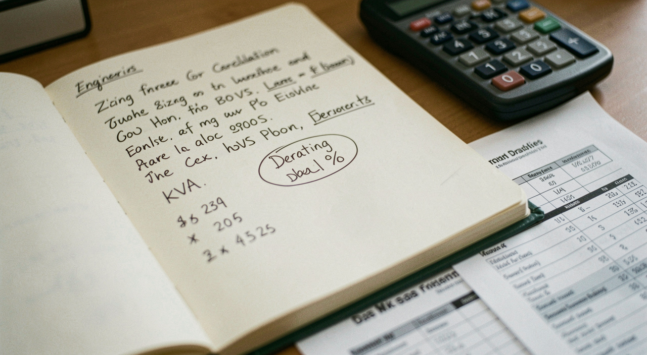
Add a margin for growth, commonly 20 to 25 per cent, before derating rather than after. Then apply the site corrections: roughly 1 per cent of output lost per 100 metres above 1,000 metres of altitude, and roughly 2 per cent per 5 degrees Celsius above 40 degrees ambient, with the manufacturer's own correction table taking precedence.
In the worked example, 353 kVA of running load plus a 20 per cent margin gives 424 kVA, and a site at 45 degrees and 1,200 metres pushes the requirement to around 455 kVA. The next standard frame is a 500 kVA set, and it should be bought on its standby rating if the duty is standby and on its prime rating if it will run regularly, a distinction set out in the generator set section.
Step 6: check it against a real machine
Take the required figure to the platform pages and see where it lands. Around 500 kVA sits comfortably on a 19 litre inline six, which on the imported platforms means the range described in the Cummins page and, on the domestic platforms, the mid-range blocks covered in the Shangchai page. Then read the datasheet in the order recommended in the technical datasheet page, correcting each candidate to your own conditions before comparing anything.
Read next
The same arithmetic applied to one property is worked through in sizing a rural house standby set, and against a weak grid in the rural Spain profile.
Read the candidate datasheets in the right order once the requirement is fixed: the technical datasheet page explains the blocks and the traps.
For where each output figure lands on a real engine, see the platform pages under the generator set section.
For the installation constraints that can take back what this calculation gave you, ventilation and exhaust routing above all, read the case studies section, and the documentation library for the rest of the project file.
The same arithmetic written for a small unit is set out in the load list a small workshop can write.