Genset Digest / Industrial Blowers & Process Air / Dedusting blower
Dedusting Blower
A dedusting fan is sized by the circuit it serves, from the capture hood to the stack, and by the gas condition at the point it is measured. This page works through where the pressure goes, how the filter's share rises across the bag life, and why wear becomes an imbalance problem before it becomes a hole.
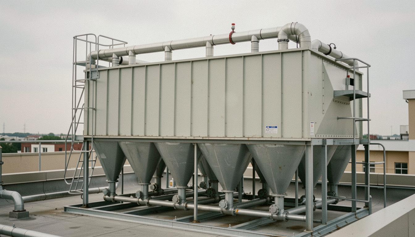
A dedusting fan is sized by the system it serves, not by the dust it moves. The chain runs from the capture hood, through the ductwork, through the filter, into the fan and out of the stack, and each element takes a share of the pressure. Get the total right and the hood holds its face velocity. Get it wrong and the plant has an expensive machine that makes noise while dust escapes at the point of generation.
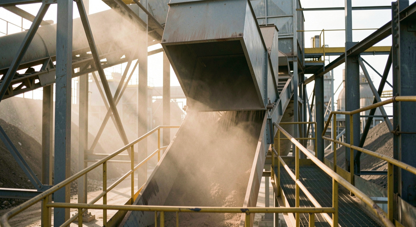
In a sintering plant and a blast furnace stock house the problem is compounded by the character of the dust: it is fine, abrasive, sometimes hot, and produced in quantities that fill a filter hopper faster than most operators expect.
Where the pressure goes
A typical fabric filter installation carries a total system resistance of 3 to 6 kilopascals at design flow. The filter itself accounts for a substantial part of that, and its share is not constant: a clean bag set may run at 1.0 kilopascal, a well-conditioned set at 1.5 to 2.0, and a set approaching replacement at 2.5 or more. A fan selected only for the clean condition will not hold the hood velocity by the end of the bag life.
The rest of the resistance is ductwork, bends, dampers and the discharge stack, which are fixed once installed and are therefore the part worth getting right on paper. Long runs with several tight radius bends can quietly account for a kilopascal on their own.
| Element | Typical share of system resistance | Changes over time |
|---|---|---|
| Capture hood and entry | 0.2 to 0.6 kPa | No, unless the hood is modified |
| Ductwork and bends | 0.5 to 1.5 kPa | Yes, if dust settles in the duct |
| Fabric filter | 1.0 to 2.5 kPa | Yes, rises across the bag life |
| Damper or vane | 0.1 to 0.8 kPa | Depends on the control method |
| Stack and discharge | 0.2 to 0.5 kPa | No |
Sizing for the sintering machine
The main exhaust fan of a sinter strand is a different order of machine altogether: it draws air down through the sinter bed, works at a large negative gauge pressure, typically in the region of minus 15 to minus 18 kilopascals, and handles volumes measured in thousands of cubic metres per minute. Its duty is set by the permeability of the bed rather than by a duct calculation, which means the fan has to hold suction across a range of bed conditions rather than at a single design point.
The secondary dedusting fans around the strand, on the discharge end, the screening station and the transfer points, are the ones a plant engineer more often has to specify. Those follow the ordinary hood and filter arithmetic, with two additions: the gas can be hot enough at the discharge end to change the density and therefore the mass the fan is really moving, and the dust load is abrasive enough to make blade wear the dominant maintenance item.
A fan curve is drawn for a stated gas density. Air at 150 degrees Celsius is roughly 70 per cent as dense as air at 20 degrees, so the same volumetric flow represents far less mass and far less pressure rise. Every dedusting specification should state the gas temperature, the moisture content and the altitude alongside the volume, or the machine will be selected for a gas that does not exist on the site.
Wear, and how it is designed around
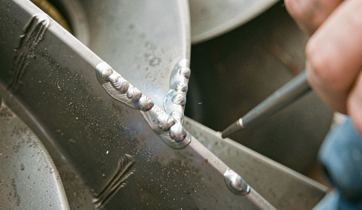
Dust that passes through a fan removes metal from the blade tips and from the shroud, and it does so unevenly, which puts the rotor out of balance long before it wears through. Three answers are used, usually in combination. Backward-inclined blades in wear-resistant plate, hardfacing or replaceable wear strips on the leading edges, and installation on the clean side of the filter wherever the layout allows it.
The clean-side option is the most effective and the most often abandoned for layout reasons. Where it cannot be had, vibration monitoring on the fan bearings becomes the primary early warning, because it detects the developing imbalance before it becomes a shaft problem. The equivalent discipline on the generating side of a plant, proving a machine before it is needed rather than after, is described in the load bank testing guide.
Control and running cost
A dedusting fan typically runs whenever the plant runs, which means 7,000 to 8,000 hours a year, which means the control method decides a large annual bill. Throttling with an outlet damper is the cheapest to install and the most expensive to own. Inlet vane control recovers part of the loss. Variable speed drive control recovers most of it, and has the additional benefit of allowing the fan to compensate for rising filter resistance across the bag life without an operator touching anything.
A worked version of that trade-off, with the constraints a real retrofit brief adds around it, is set out in the sintering machine loop cooling blower profile. For the other two duties in this section, the combustion blower page covers the high-pressure case and the section index compares all three side by side.
Read next
The companion duty, high pressure against a fuel-linked control loop, is covered in the combustion blower page.
For a project-level example of sizing a cooling and dedusting retrofit under noise and duty cycle limits, read the sintering machine cooling blower profile.
For the low-pressure, high-volume end of the same plant, the Stelmor blower page shows how differently a cooling duty behaves, and the case studies section collects the installation profiles.
The intake side of the same problem is set out in the ground-coupled intake.